HPCLJCP1510Repair: Unterschied zwischen den Versionen
| (2 dazwischenliegende Versionen desselben Benutzers werden nicht angezeigt) | |||
| Zeile 2: | Zeile 2: | ||
|name = HP CP1515n Color Calibration | |name = HP CP1515n Color Calibration | ||
|kategorie = Sonstiges | |kategorie = Sonstiges | ||
| − | |status = | + | |status = stable |
|autor = [[Benutzer:omicron|omicron]] | |autor = [[Benutzer:omicron|omicron]] | ||
|beschreibung = Fix Color Calibration of HP CP 1515n Printer | |beschreibung = Fix Color Calibration of HP CP 1515n Printer | ||
| Zeile 67: | Zeile 67: | ||
** The left cover for your own safety, because the high voltage components are located beneath it | ** The left cover for your own safety, because the high voltage components are located beneath it | ||
* But (as always) be careful not to touch any live parts when the printer is connected to power! | * But (as always) be careful not to touch any live parts when the printer is connected to power! | ||
| + | * Instead of stretching the springs, you can of course replace them by a new one. However, it must be replaced by a spring with the appropriate length, stiffness and diameter, which most people (including myself) do not have at hand. | ||
=Long Version= | =Long Version= | ||
| Zeile 77: | Zeile 78: | ||
My next attempt consisted of 4 things (I was quite in despair): | My next attempt consisted of 4 things (I was quite in despair): | ||
| − | * I temporarily dismounted the front top part of the ITB | + | * I temporarily dismounted the front top part of the ITB and remounted it afterwards without doing any real change. |
* I dismounted the two coil springs which seem to tighten the belt and stretched them with two pairs of pliers - for the purpose of increasing the spring stiffness (in a very amateurish way) | * I dismounted the two coil springs which seem to tighten the belt and stretched them with two pairs of pliers - for the purpose of increasing the spring stiffness (in a very amateurish way) | ||
* I again turned all 3 trimmers in the exact position where the calibration initially worked | * I again turned all 3 trimmers in the exact position where the calibration initially worked | ||
| Zeile 96: | Zeile 97: | ||
Finally, I did some sensitivity analysis of successful calibration to the positions of the 3 trimmers - starting from the now hopefully well-reproducible good position of VR1. | Finally, I did some sensitivity analysis of successful calibration to the positions of the 3 trimmers - starting from the now hopefully well-reproducible good position of VR1. | ||
| − | + | As it turned out, I obviously initially hit the correct trimmer position of VR1 by chance: The trimmer position needs to be in a range of about +/- 5-10 degrees to be optimal, i. e. leading to a correct calibration. | |
| − | As it turned out, I | ||
Aktuelle Version vom 20. September 2015, 20:22 Uhr
Status: stable | |
|---|---|

| |
| Beschreibung | Fix Color Calibration of HP CP 1515n Printer |
| Autor: | omicron |
| Version | 1.0 |
| PayPal | |
Objective
The objective of this project is to fix a HP LaserJet CP 1510 Series printer having color calibration issues.
Short version
Problem
- Color calibration of a HP Color LaserJet 1510 Series Printer (e.g. CP 1515n) is not working correctly (see top left part of image)
- All attempts to fix the problem otherwise have failed:
- Update to latest firmware
- Repeated calibration (> 3 times)
- NVRAM reset
- Reset to Factory defaults from menu
- The following other attempts were not done:
- Replace the ITB assembly (cost reasons)
- Buy set of original HP toner (cost reasons)
Solution
Common
- Print diagnostics page using the printer menu (for later comparison).
- Get the service manual (Google for "HP Color Laserjet CP1215 CP1515 CP1518 Service Manual")
- Follow the instructions for removing the Intermediate Transfer Belt (ITB)
Part 1: Trimmer
- Turn the ITB assembly upside down
- Find the two small PCBs where the wires end
- Take a photo of the positions of all 3 trimmer (labelled VR1, VR1 and VR2 on the two PCBs)
- Find the trimmer labelled VR1 on the right of the two PCBs (the board with 2 trimmers on it). Example:
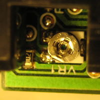
- Turn VR1 clockwise. For me, 90 degrees worked. However, the calibration seems to be quite sensitive to the exact position. Hence you have do some trial-and-error here. Example:
- Follow the instructions of the service manual for re-installing the ITB assembly
- Connect printer to power
- Start a color calibration
- Print diagnostics page and compare with diagnostics page before the fix
- Done (or try another trimmer position)
- If no trimmer position works, see long version


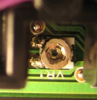
Part 2: Springs
- Remove one spring on each side of the ITB board. The following picture shows one of them in assembled state:

- The springs are only fixed on one end. The other end (the left end in the above picture) can simply be levered out using a big screwdriver.
- Afterwards, use two pairs of pliers for stretching the springs. This is done for the purpose of increasing the spring stiffness.
- It may be sensible to turn the pliers while stretching the spring for preventing an increase or decrease of the diameter of the spring.
- Afterwards reassemble the springs. This may be a little bit tricky and took me some minutes: I used two screwdrivers: One for tensioning the spring and putting it into the right place and another smaller screwdriver for stripping the spring from the first screwdriver - while pulling the first screwdriver out and leaving the spring in its place.
Notes
- This fix will certainly break warranty. Hence, only do it with printers being out of warranty!
- The fix proved to work for a single CP1515n printer. It may have to be modified for other instances.
- If changing VR1 on right PCB does not solve the problem, try the other trimmers (But always remember the original state!)
- When testing the effect of changing the trimmer, you only need to reassemble the following components
- The ITB itself
- The print-cartridge drawer stop
- The Print-cartridge drawer
- The left cover for your own safety, because the high voltage components are located beneath it
- But (as always) be careful not to touch any live parts when the printer is connected to power!
- Instead of stretching the springs, you can of course replace them by a new one. However, it must be replaced by a spring with the appropriate length, stiffness and diameter, which most people (including myself) do not have at hand.
Long Version
Note that, if nothing else is mentioned, after each change I started calibration (at least, but usually only) twice.
Unfortunately, the short version worked only once. When I changed VR1 (see above), I also tightened the screws of the ITB. Hence there was a chance, that not the change of the trimmer led to success but the tightening of the screws. Hence, I changed back the trimmer to its original position and reassembled the printer. Then, as expected, the calibration failed again. Now I changed again the trimmer position as mentioned above and again reassembled the printer. Unfortunately, it did not work this time: Even after 3 calibrations the "L-lines" in the diagnostic page crossed each other.
Because of the above experience, I then supected a mechanical problem. Hence, I tightened the screws again. This time I used a special torque screwdriver and tightened all screws of the ITB module (which I could reach) with 1 Nm. Unfortunately, this did not help either.
My next attempt consisted of 4 things (I was quite in despair):
- I temporarily dismounted the front top part of the ITB and remounted it afterwards without doing any real change.
- I dismounted the two coil springs which seem to tighten the belt and stretched them with two pairs of pliers - for the purpose of increasing the spring stiffness (in a very amateurish way)
- I again turned all 3 trimmers in the exact position where the calibration initially worked
- I dismounted the 2 PCBs and removed the plastic covers covering the component side and cleaned them (for details see below)
After reassembling everything again, it worked again.
Now I again wanted to know, which change was the successful one (i. e. was it the cleaning of the PCB or some mechanical change), I turned the trimmer back to its original position. Now the calibration failed again. But after carefully turning the trimmer again into its known-working position, calibation was successful again.
Finally, I did some sensitivity analysis of the calibation working or not for various trimmer positions. During this analysis, at some point it did not work again. I then only increased the spring stiffness (again) without changing anything (apart from the "good" VR1 position). Afterwards, it worked again.
Then I inspected the mechanism which tightens the belt a little bit more carefully. From the beginning on, I noticed two rather loose plastic parts near the springs, which function I could not identify. After having reassembled the springs I noticed that they have to do with the tightening mechanism. The two plastic parts are levers to relax and tighten the ITB. However, I did not found any information about this feature in any document - neither the printer manual nor the service manual! Additionally, this tightening mechanism can be accessed even if the printer is fully mounted - with only the front door open (TODO: pictures!). Hence, it may have been enough to relax and re-tighten the ITB after re-assembling the printer instead of having to increase the spring stiffness at all! The re-tightening might increase the fit of the ITB assembly inside the printer.
Hence the original problem seems to have 2 causes:
- The spring stiffness of the ITB springs or the correct fit of the ITB in reassembled state
- The position of VR1
Finally, I did some sensitivity analysis of successful calibration to the positions of the 3 trimmers - starting from the now hopefully well-reproducible good position of VR1.
As it turned out, I obviously initially hit the correct trimmer position of VR1 by chance: The trimmer position needs to be in a range of about +/- 5-10 degrees to be optimal, i. e. leading to a correct calibration.