Co2 Monitor: Unterschied zwischen den Versionen
| (12 dazwischenliegende Versionen von 3 Benutzern werden nicht angezeigt) | |||
| Zeile 2: | Zeile 2: | ||
|name = CO² Monitor | |name = CO² Monitor | ||
|status = stable | |status = stable | ||
| − | |autor = [[Benutzer:schinken|schinken]] | + | |autor = [[Benutzer:foosinn|foosinn]], [[Benutzer:schinken|schinken]] |
|beschreibung = IoT CO² Sensor | |beschreibung = IoT CO² Sensor | ||
|image = cat_co2_sensor.jpg | |image = cat_co2_sensor.jpg | ||
| Zeile 11: | Zeile 11: | ||
[[Category:Hardware]] | [[Category:Hardware]] | ||
| − | == | + | ==ESP Home & ESP C3 Super Mini Version== |
| − | + | ===Description=== | |
| − | + | Since migrating to Homeassistant we have also migrated all of our ESPs to ESPHome. This allowes easy maintenance and OTA updates. | |
| + | We have also designed a custom case to house the ESP C3 and the Cables. | ||
| − | == Hardware == | + | ===Hardware === |
| + | |||
| + | As before you have to solder one additional Pin to the TFA Dostmann CO2-Sensor AirCO2ntrol Sensor. | ||
| + | {| class="wikitable" | ||
| + | |+ | ||
| + | Wiring | ||
| + | !Sensor | ||
| + | !Usage | ||
| + | !ESP32 C3 Super Mini | ||
| + | |- | ||
| + | |Top pin | ||
| + | |Ground | ||
| + | |GND | ||
| + | |- | ||
| + | | Second pin | ||
| + | |Clock | ||
| + | |Pin 6 | ||
| + | |- | ||
| + | | Third pin | ||
| + | |Data | ||
| + | |Pin 5 | ||
| + | |- | ||
| + | |Lowest pin | ||
| + | |Power | ||
| + | |5V | ||
| + | |} | ||
| + | |||
| + | We have designed a case which provides additional space for the sensor. You can download the backplate form [https://www.printables.com/model/875532-airco2ntrol-co2-sensor-with-esp32-c3-super-mini Printables] or [https://cad.onshape.com/documents/ccde53a577602418aef280f7/w/8e4bb189e986f0ba2e6a2094/e/38f7d6b6b42aff2a94232abd?renderMode=0&uiState=663e6f25f2284c69c3e4a141 Onshape] | ||
| + | |||
| + | [[Datei:Co2-sensor-side.jpg|200x200px]] [[Datei:Co2 sensor back.jpg|rahmenlos|200x200px]] [[Datei:Co2 inside.jpg|rahmenlos|267x267px]] | ||
| + | |||
| + | ===Software=== | ||
| + | |||
| + | Extend you ESPHome config using this code block. According to some documentations the clock and data pins are swapped on some models. | ||
| + | |||
| + | <syntaxhighlight lang="yaml"> | ||
| + | sensor: | ||
| + | - platform: zyaura | ||
| + | clock_pin: 6 | ||
| + | data_pin: 5 | ||
| + | co2: | ||
| + | name: "Hackcenter CO2" | ||
| + | temperature: | ||
| + | name: "Hackcenter Temperature" | ||
| + | </syntaxhighlight> | ||
| + | ==DIY Version== | ||
| + | |||
| + | ===Description=== | ||
| + | |||
| + | Someday a [https://amzn.to/2HPV9OG TFA Dostmann CO2-Sensor AirCO2ntrol] appeared in our hackerspace - but the CO² reading couldn't be easily acquired through USB or any other connector. There are some implementations using [https://github.com/fablabnbg/airco2ntrold python] or nodejs, but they require a raspberry pi or at least a PC nearby to read the values to publish and store them somewhere. | ||
| + | |||
| + | Nowadays ESP8266, NodeMCU or in our case a Wemos D1 mini (which also has a ESP8266 on it) exist and is totally suitable for the job! Sadly, on the TFA Dostmann there's only a USB interface on the outside, and our Microcontroller does not support USB natively. So we opened the sensor and found a "CALIB" interface | ||
| + | |||
| + | ===Hardware=== | ||
Inside the TDA Dostmann CO² sensor, there's a CALIB interface, which consist of four PINs. GND and 5V can easily be determined using a multimeter with continuity test. These PINs are directly connected to the USB port and can be used to power our microcontroller. The other 2 PINs in the middle seem to send some data. After connecting them to a oscilloscope one PIN was obviously just clock, and the other data. | Inside the TDA Dostmann CO² sensor, there's a CALIB interface, which consist of four PINs. GND and 5V can easily be determined using a multimeter with continuity test. These PINs are directly connected to the USB port and can be used to power our microcontroller. The other 2 PINs in the middle seem to send some data. After connecting them to a oscilloscope one PIN was obviously just clock, and the other data. | ||
| Zeile 28: | Zeile 82: | ||
</gallery> | </gallery> | ||
| + | Test readings using [https://sigrok.org/ SIGROK] and a logic analyser can be found on [https://github.com/b4ckspace/esp8266-co2monitor/tree/master/doc/sigrok-captures b4ckspace/esp8266-co2monitor/sigrok-captures]. | ||
| − | == Software == | + | ===Software === |
The signals look like they're just I2C, but actually they're not. Using the scope to decode the data failed - the same is true using the Wemos. After wiring up the sensor to the Wemos we used an external interrupt on the clock pin and a digitalRead on the data pin which is basically "bit banging". | The signals look like they're just I2C, but actually they're not. Using the scope to decode the data failed - the same is true using the Wemos. After wiring up the sensor to the Wemos we used an external interrupt on the clock pin and a digitalRead on the data pin which is basically "bit banging". | ||
Aktuelle Version vom 12. Mai 2024, 22:48 Uhr
Status: stable | |
|---|---|

| |
| Beschreibung | IoT CO² Sensor |
| Autor: | foosinn, schinken |
| PayPal | |
ESP Home & ESP C3 Super Mini Version
Description
Since migrating to Homeassistant we have also migrated all of our ESPs to ESPHome. This allowes easy maintenance and OTA updates.
We have also designed a custom case to house the ESP C3 and the Cables.
Hardware
As before you have to solder one additional Pin to the TFA Dostmann CO2-Sensor AirCO2ntrol Sensor.
| Sensor | Usage | ESP32 C3 Super Mini |
|---|---|---|
| Top pin | Ground | GND |
| Second pin | Clock | Pin 6 |
| Third pin | Data | Pin 5 |
| Lowest pin | Power | 5V |
We have designed a case which provides additional space for the sensor. You can download the backplate form Printables or Onshape


Software
Extend you ESPHome config using this code block. According to some documentations the clock and data pins are swapped on some models.
sensor:
  - platform: zyaura
    clock_pin: 6
    data_pin: 5
    co2:
      name: "Hackcenter CO2"
    temperature:
      name: "Hackcenter Temperature"
DIY Version
Description
Someday a TFA Dostmann CO2-Sensor AirCO2ntrol appeared in our hackerspace - but the CO² reading couldn't be easily acquired through USB or any other connector. There are some implementations using python or nodejs, but they require a raspberry pi or at least a PC nearby to read the values to publish and store them somewhere.
Nowadays ESP8266, NodeMCU or in our case a Wemos D1 mini (which also has a ESP8266 on it) exist and is totally suitable for the job! Sadly, on the TFA Dostmann there's only a USB interface on the outside, and our Microcontroller does not support USB natively. So we opened the sensor and found a "CALIB" interface
Hardware
Inside the TDA Dostmann CO² sensor, there's a CALIB interface, which consist of four PINs. GND and 5V can easily be determined using a multimeter with continuity test. These PINs are directly connected to the USB port and can be used to power our microcontroller. The other 2 PINs in the middle seem to send some data. After connecting them to a oscilloscope one PIN was obviously just clock, and the other data.
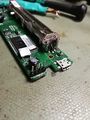
LTR: GND, Clock, Data and 5V
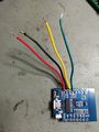
Add wires
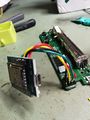
Connected!


Test readings using SIGROK and a logic analyser can be found on b4ckspace/esp8266-co2monitor/sigrok-captures.
Software
The signals look like they're just I2C, but actually they're not. Using the scope to decode the data failed - the same is true using the Wemos. After wiring up the sensor to the Wemos we used an external interrupt on the clock pin and a digitalRead on the data pin which is basically "bit banging".
The results were promising: Using a simple python script and the documentation from another manufacturer, we were able to verify the checksum. Also implementing the decode of the data was quite simple using the PDF:
case 0x50:
 co2Measurement = (data[IDX_MSB] << 8) | data[IDX_LSB];
 break;
case 0x42:
 temperature = ((data[IDX_MSB] << 8) | data[IDX_LSB]) / 16.0 - 273.15;
 break;
The last thing to do was connecting to wifi and publishing the data on MQTT. The source code can be found on GitHub and is licensed under the MIT-License.